2026 Top Car Audio Installation Guide for Global Buyers?

Buying a new car audio system across borders can feel exciting, but installation rarely works as a simple plug-and-play task. Vehicle wiring, dashboard space, speaker depth, factory amplifiers, and regional voltage standards can vary significantly. This 2026 guide introduces practical car audio installation methods for global buyers, from component selection to final sound checks.

Richard Clark, a respected car-audio educator and former IASCA founder, offered a useful principle: “The best system is the one that sounds best to you.” That idea still matters. A powerful subwoofer may impress in a showroom, yet it can sound uncontrolled inside a small cabin. A modest component set may perform better after careful tuning, secure mounting, and correct phase alignment.

Details matter.

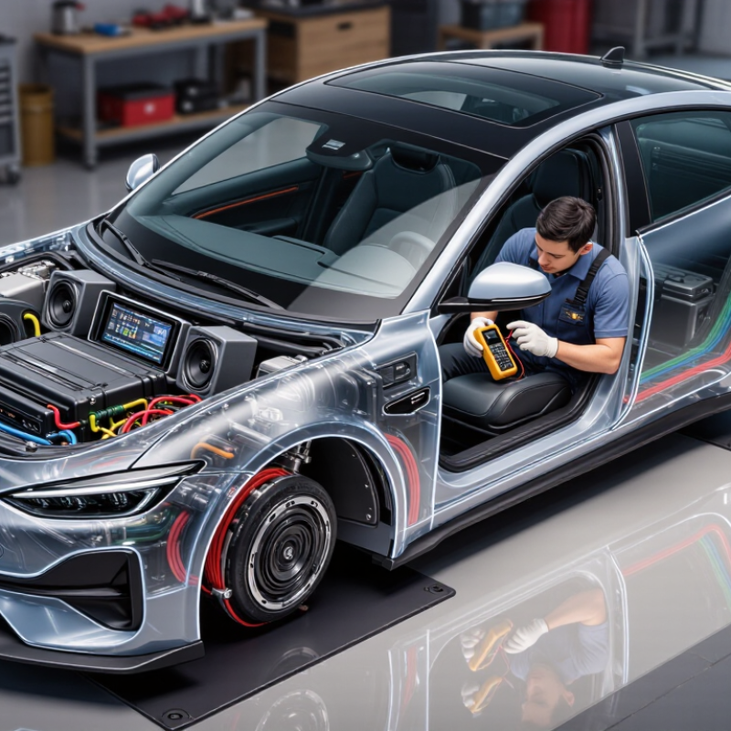
Experienced installers measure door cavities before ordering speakers. They inspect factory connectors, protect wiring from sharp metal, and test every channel before closing the trim. Buyers should also confirm warranty terms, professional qualifications, and local electrical requirements. Some imported products may fit physically but lack suitable harnesses or documentation.

This guide is not a promise of perfection. Vehicle interiors differ, and online measurements can be incomplete. Even skilled technicians sometimes overlook a noisy ground point or underestimate factory signal processing. That is why reliable installation includes testing, listening, documenting changes, and revisiting weak results. Global buyers deserve more than impressive specifications. They need clear compatibility checks, honest limitations, and a system that remains safe, balanced, and enjoyable during everyday driving.

2026 Top Car Audio Installation Guide for Global Buyers?

Assess Vehicle Power: 12 V Systems, 14.4 V Charging, and Battery Load

2026 Top Car Audio Installation Guide for Global Buyers

Assessing vehicle power starts with the battery, not the amplifier. A vehicle’s “12-volt” system is nominal, not constant. SAE J537 describes the common six-cell battery format, while a healthy rested battery usually measures about 12.6 volts. With the engine running, charging voltage often rises toward 13.8–14.4 volts. Modern smart charging systems can vary outside that range.

Measure it yourself.

A 1,000-watt amplifier can demand about 69 amps at 14.4 volts before efficiency losses. At 80% efficiency, the demand approaches 87 amps. At engine-off voltage, the same output requires more current. The U.S. Department of Energy’s vehicle technology data highlights how accessory loads reduce available electrical energy, especially during idle and low-speed driving. Headlights, ventilation, heated seats, and engine controls already consume part of the alternator’s capacity.

Do not trust peak wattage alone. Use continuous RMS power, amplifier efficiency, and fuse ratings. A clamp meter is useful during bass-heavy testing. Watch for dimming lights, voltage below roughly 13 volts while charging, or repeated battery discharge. These symptoms suggest insufficient reserve capacity or poor wiring. I still recheck ground points after installation; a clean calculation cannot reveal every weak connection. A 14.4-volt reading also does not prove the alternator has enough current for the new system. Allow practical headroom, because real vehicles rarely behave like laboratory benches.

Match Speakers and Amplifiers by RMS Power, Impedance, and 85–95 dB Sensitivity

When installing car audio for overseas buyers, I match speakers and amplifiers by RMS power first. A speaker rated at 75 watts RMS should receive roughly 50–100 watts RMS per channel. Peak power is less useful for daily listening. It often makes equipment look stronger than it performs.

Impedance must match the amplifier’s safe operating range. A 4-ohm speaker usually offers an easier load, while a 2-ohm model can demand much more current. Check the amplifier manual before wiring anything. Incorrect connections may create heat, distortion, or early failure. I also measure cable routes carefully, because cramped panels can damage insulation during installation.

Sensitivity between 85 and 95 dB works well for many vehicles. Higher sensitivity produces more volume from the same amplifier power. This matters when using a modest factory electrical system. However, sensitivity figures are not always measured under identical conditions. Treat them as useful guidance, not absolute truth. I once chose a highly sensitive speaker that sounded harsh in a reflective cabin. The numbers were correct, but the installation was not. Door treatment, speaker positioning, and crossover settings changed the result more than expected. Leave headroom, secure every connection, and test at moderate volume before final panel assembly.

Plan Safe Wiring with 4–8 Ω Loads, Proper Fusing, and ISO 16750 Practices

2026 Top Car Audio Installation Guide for Global Buyers

A safe car audio installation begins with the load, not the speaker size. Most aftermarket speakers present 4–8 Ω loads, but impedance can change with frequency. Check the amplifier’s stable impedance before connecting multiple speakers. Two 4 Ω speakers wired in parallel can create a 2 Ω load. That may overheat an unsuitable amplifier.

Place the main fuse close to the battery, usually within a short protected distance. Select its rating from the cable’s current capacity, not the amplifier’s maximum marketing figure. Use flexible automotive cable, secure it away from sharp metal, and protect every firewall opening with a grommet. Ground the amplifier to clean, unpainted chassis metal. Keep the ground short. It sounds simple, but poor grounding remains a common installation failure.

ISO 16750 practices encourage attention to vibration, temperature changes, moisture, and electrical transients. Support heavy components with firm brackets, leaving no connector hanging under road vibration. Add strain relief near terminals. Test the system with the engine off, then running, while checking voltage, heat, and fuse behavior. A thermal camera is useful, though careful hand checks can reveal abnormal warmth. My early wiring plans looked neat but ignored service access. That was a mistake. Leave room for inspection and replacement. Verify polarity, measure resistance, and retest after several drives. Small assumptions can become expensive faults.

Install Head Units, Speakers, Subwoofers, and Amplifiers in a Stepwise Sequence

A reliable car audio installation begins with the head unit. It controls signal quality, connectivity, and system adjustment. Disconnect the battery, confirm the vehicle wiring, and test every function before securing the dashboard.

Grand View Research estimates the global automotive audio market will grow at about 7% annually through 2030. That growth reflects stronger demand for integrated entertainment systems, not careless upgrades.

Install the speakers after confirming their size, depth, and mounting points. Use foam rings around each speaker to reduce door-panel vibration. Check polarity with a brief low-volume test.

Reversed wiring can weaken bass noticeably. I once skipped this check and spent an hour correcting a thin, hollow sound. Small mistakes become expensive later.

Place the subwoofer after the main speakers work correctly. Then connect the amplifier, keeping signal cables separate from power cables where practical. Set gain conservatively; gain is not a volume control.

The Consumer Technology Association reported that connected-car technologies remain a major part of consumer electronics demand in its 2024 industry forecast. That makes clean integration increasingly important.

Allow space for ventilation, protect cables from sharp metal, and secure every connection before tuning. A frequency sweep and familiar vocal recording reveal problems better than loud music. Recheck the system after several drives; panels can loosen, and my first installation was not perfect.

Tune the System Using 20 Hz–20 kHz Response, Crossover Slopes, and SPL Metrics

2026 Top Car Audio Installation Guide for Global Buyers

Tune the System Using 20 Hz–20 kHz Response, Crossover Slopes, and SPL Metrics

A reliable car-audio tune begins with measurement, not guesswork. The IEC 60268-21 standard defines methods for measuring frequency response and sound-pressure level. Use a calibrated microphone at the driver’s ear position. Sweep from 20 Hz to 20 kHz, then record peaks, nulls, and left-right imbalance. Human hearing usually weakens near both limits, so a perfectly flat graph may not sound natural inside a moving cabin. Cabin reflections can also create narrow dips. Do not boost every dip.

Crossover settings need practical restraint. Start with a 12 or 24 dB-per-octave slope, then adjust after listening to vocals, kick drums, and cymbals. A 24 dB slope often reduces overlap, but it can expose phase errors. Check polarity and delay before adding equalization. Measure twice. The Audio Engineering Society’s technical guidance supports controlled, repeatable listening and measurement rather than relying on memory. For loudness, log average SPL and short peaks separately. IEC 61606 and ITU-R BS.1770 methods show why level weighting matters, although car cabins remain more complex. Keep peaks below harsh clipping; sustained high SPL causes fatigue and risks hearing damage. My first tuning pass often sounds too bright. That is normal. Recheck at highway speed, with the engine running, because road noise can mask bass and midrange detail. A slightly imperfect setting may feel more musical than a perfect chart.

2026 Top Car Audio Installation Guide for Global Buyers? - Tune the System Using 20 Hz–20 kHz Response, Crossover Slopes, and SPL Metrics

Installation Area Primary Objective Recommended Starting Range or Target Measurement or Setting Method Why It Matters Practical Buying and Installation Notes
System Planning Match the equipment to the vehicle cabin, listening position, and available electrical capacity. 20 Hz–20 kHz system design target; use the actual usable response of each component rather than assuming the full range. List each loudspeaker's measured or documented response, sensitivity, impedance, continuous power handling, and mounting depth. A complete system must cover the audible range without forcing a driver to reproduce frequencies outside its practical operating band. Check vehicle compatibility, battery and alternator capacity, enclosure space, wiring routes, climate conditions, and local electrical-safety requirements before purchasing.
Front Door Midbass Provide kick drum, lower musical fundamentals, and a smooth transition to the subwoofer. Typical starting passband: 60–2,500 Hz, adjusted for the speaker, door treatment, and listening position. Apply a high-pass filter near 50–80 Hz and a low-pass filter near 2–3 kHz, then verify the result with pink noise or a frequency sweep. Filtering reduces low-frequency excursion and prevents excessive overlap with the tweeter and subwoofer. Use a rigid mounting adapter, seal unused door openings, protect against moisture, and confirm that the window mechanism clears the speaker.
Tweeter Reproduce upper midrange and treble with controlled directivity and low distortion. Typical starting high-pass point: 2.5–4 kHz; use a steeper slope when the tweeter has limited low-frequency power handling. Start with a Linkwitz–Riley 24 dB/octave high-pass filter, then adjust the crossover point and level after measuring on-axis and at the main listening position. A suitable crossover protects the tweeter and helps create a stable center image without harsh overlap. Do not choose a crossover point solely from the published frequency range; consider the tweeter's resonance, power handling, dispersion, and installation angle.
Subwoofer Extend low-frequency output while blending smoothly with the front stage. Typical operating band: 20–80 Hz; a common initial low-pass setting is 70–90 Hz. Use a low-pass filter, set the enclosure according to its design, and verify cone excursion, polarity, and phase at the crossover region. Correct integration prevents a boomy upper-bass peak or a weak transition between the subwoofer and door midbass. For ported enclosures, avoid operating substantially below the enclosure tuning frequency without suitable protection. Secure the enclosure against movement.
Crossover Slope Control how rapidly each driver is attenuated outside its intended band. Common options: 12, 18, or 24 dB/octave; 24 dB/octave is a useful initial setting for many active systems. Keep the filter family and acoustic target consistent where possible. Confirm the combined acoustic response rather than relying only on DSP display values. Filter slope affects driver protection, phase behavior, overlap, and the amount of equalization required. A higher electrical slope does not always produce the same acoustic slope because the vehicle, enclosure, and speaker's natural roll-off also contribute.
Crossover Alignment Make adjacent drivers combine constructively through the crossover region. Begin with matched crossover frequencies and a nominal 0° phase relationship; test polarity and delay settings. Measure the response around the crossover frequency while changing polarity or delay. Select the setting that produces the smoothest, strongest transition without a narrow cancellation dip. Correct alignment improves impact, tonal balance, and image stability at the main listening position. Do not assume that reversing speaker polarity is always wrong; the correct setting depends on acoustic offset, filter type, and installation geometry.
Time Alignment Compensate for different distances between the listener and each driver. Use measured distances in centimeters or inches; acoustic delay is approximately 2.92 ms per meter of path-length difference. Measure from the main listening position to each acoustic center, enter the distances into the processor, and fine-tune using a centered vocal recording. Time alignment can improve the perceived center image and reduce smearing between left and right channels. Use the intended primary listening position as the reference. A setting optimized for one seat may not be optimal for all passengers.
Equalization Reduce broad tonal imbalances created by the cabin and installation. Prioritize broad corrections of approximately ±3 to ±6 dB; avoid large boosts when repositioning or installation changes can solve the problem. Measure with a calibrated microphone at the listening position using pink noise or sweeps. Apply cuts before boosts and recheck after every major change. Moderate equalization preserves amplifier headroom and usually sounds more natural than aggressive narrow-band boosting. Use parametric EQ with adjustable frequency, gain, and Q. Avoid chasing every small peak caused by reflections or microphone-position changes.
Frequency-Response Verification Confirm that the complete system covers the intended audible range with a balanced response. Inspect approximately 20 Hz–20 kHz, with special attention to crossover regions and the lower bass area below 80 Hz. Use repeatable microphone placement, consistent volume, a calibrated measurement path, and smoothing appropriate for the diagnostic task. Listening alone can miss narrow cancellations, polarity errors, and response changes caused by seat position. Interpret measurements in the vehicle environment; cabin gain, reflections, glass surfaces, seat absorption, and microphone placement affect the result.
SPL Level Setting Achieve adequate output while maintaining low distortion and safe listening conditions. Use a calibrated reference level around 75–85 dB SPL at the main listening position for tuning; short-term peaks may be higher. Use an SPL meter or calibrated measurement microphone with a defined weighting and slow or fast response setting. Record the reference volume before tuning. Consistent level makes comparisons meaningful and helps prevent excessive gain, clipping, and hearing-risk exposure. SPL readings depend on weighting, bandwidth, microphone location, and measurement duration. Avoid prolonged exposure to high sound levels.
Gain Structure Maximize usable dynamic range while preventing clipping at the source, processor, and amplifier. Set source and processor levels below clipping, then raise amplifier gain only as needed; avoid using gain as a volume control. Use a test tone appropriate to the system, an oscilloscope, distortion analyzer, or calibrated clipping indicator. Verify every signal path. Correct gain structure reduces hiss at low volume and distortion at high volume. Test with the loudest expected source level and confirm that bass boosts or EQ changes do not create clipping headroom problems.
Impedance and Power Ensure the amplifier can safely drive the connected load and the speaker can handle the applied power. Use the speaker's rated nominal impedance and continuous power specifications; do not treat peak power as a continuous operating target. Confirm amplifier stability at the actual wired impedance, use the correct fuse rating, and verify cable size against current demand and cable length. Impedance mismatch, inadequate wiring, or insufficient ventilation can cause protection shutdown, voltage drop, or equipment damage. Follow electrical standards for fusing near the battery, grounding, cable protection, ventilation, and secure termination.
Final Listening Check Validate tonal balance, imaging, reliability, and usability under real driving conditions. Check several recordings with vocals, bass transients, acoustic instruments, and dense mixes at low, medium, and moderate-high levels. Listen from the normal driving position, then compare with the final measurement. Recheck rattles, thermal behavior, panel clearance, and control access. Measurements identify problems, while controlled listening confirms whether the system is coherent and enjoyable in the vehicle. Document final crossover points, slopes, delays, EQ values, reference volume, fuse ratings, and wiring changes for future maintenance.